This is a FM transmitter circuit using Maxim semiconductors IC MAX2606. In the circuit the nominal frequency is set to 100 Mhz by inductor L1, (390nH) . The left and right channel audio signals from your source are added by R3 and R4, and attenuated by the POT R2. R2 can be used as a volume control .POT R1 can be used to select a channel of transmission between 88Mhz and 108Mhz.Use 80 cm long wire as the antena.
* Use a battery for powering the circuit.It will reduce noise.
* An FM antenna from a old radio is a better option than the wire antenna.
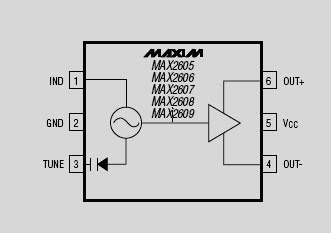
IC MAX2606 Description
The MAX2605-MAX2609 are compact, high-performance intermediate-frequency (IF) voltage-controlled oscillators (VCOs) designed specifically for demanding portable wireless communication systems. They combine monolithic construction with low-noise, low-power operation in a tiny 6-pin SOT23 package.
These low-noise VCOs feature an on-chip varactor and feedback capacitors that eliminate the need for external tuning elements, making the MAX2605-MAX2609 ideal for portable systems. Only an external inductor is required to set the oscillation frequency. In addition, an integrated differential output buffer is provided for driving a mixer or prescaler. The buffer output is capable of supplying up to -8dBm (differential) with a simple power match. It also provides isolation from load impedance variations.
The MAX2605-MAX2609 operate from a single +2.7V to +5.5V supply and offer low current consumption. These IF oscillators can cover the 45MHz to 650MHz frequency range.

IC MAX2606 Absolute Maximum Rating


